Condenser — Vapor In, Oil Out
A shell-and-tube condenser receives hot pyrolysis vapors, cools them with water flowing through internal tubes, and separates condensed liquid pyrolysis oil from non-condensable syngas — the fundamental separation step after the reactor.
Beyond definitions
Planning to start a Plastic Pyrolysis business?
Get the full business understanding — capex, regulations, machinery, vendor questions, and risk checks before you commit capital.
How to read this sketch
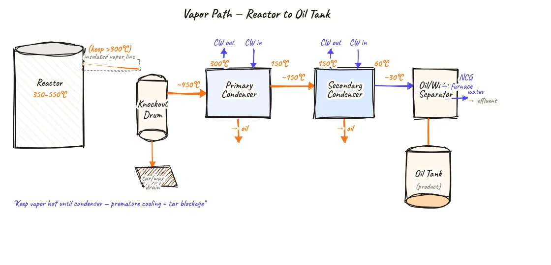
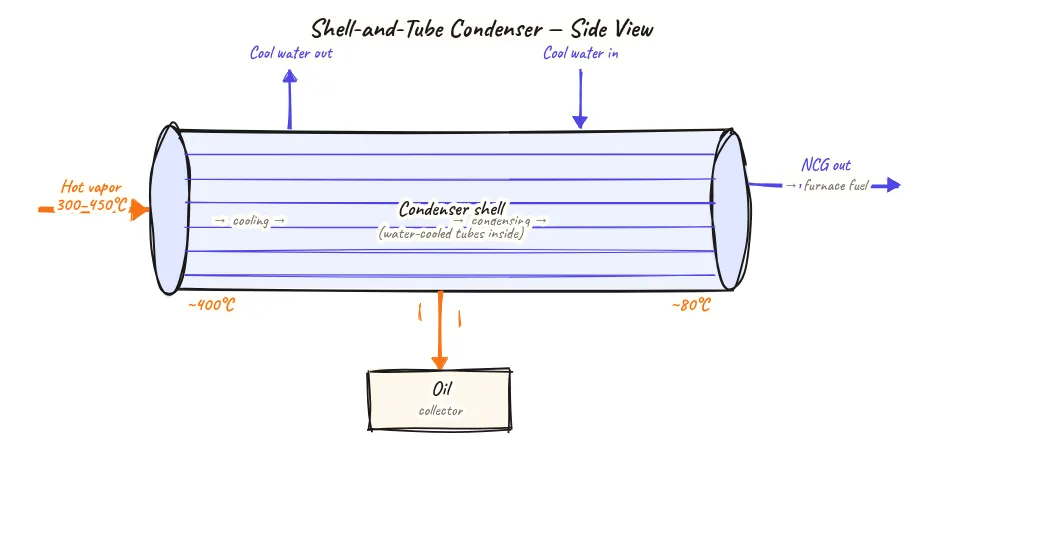
This is a side (elevation) cross-section view of the condenser. Read it as follows:
- Shell (outer vessel): The large envelope of the heat exchanger. Hot vapors flow through the shell side.
- Tube bundle (interior lines): Multiple parallel tubes shown in cross-section. Cooling water flows through the tubes.
- Vapor inlet (left top): Hot mixed vapors enter from the reactor/vapor line.
- Cooling water (tubes, left-right): Cold water enters one end and warm water exits the other — counter-flow direction shown by opposing arrows.
- Oil drain (bottom): Condensed liquid pyrolysis oil accumulates at the bottom of the shell and drains to the oil collection tank.
- NCG outlet (right top): Non-condensable gas that could not condense exits here to the gas holder.
About this sketch
The condenser is the equipment that turns pyrolysis vapors into liquid oil. Without effective condensation, all the cracked hydrocarbons would remain as gas and leave the plant as either furnace fuel or flared emissions — no liquid product, no revenue. This diagram shows the most common condenser design for plastic pyrolysis: a shell-and-tube heat exchanger.
Hot mixed vapors from the reactor (at 350–500°C) enter the condenser on the shell side — the large outer vessel. Inside the shell, a bundle of tubes carries cooling water. As hot vapors contact the cool tube surfaces, hydrocarbons above their dew point condense into liquid oil droplets that run down and collect at the shell bottom, draining into the oil collection tank below. Cooling water enters the tube side from one end and exits warmer from the other end — a counter-flow arrangement that maximises the temperature difference between vapor and coolant along the entire heat exchanger length.
Non-condensable gas (NCG) — the hydrocarbons that remain gaseous even at the condenser's lowest temperature — exits from the top or end of the shell on the gas outlet line to the NCG handling loop. The split between how much condenses (oil) and how much remains as gas depends on the cooling water temperature, the condenser area, and the composition of the vapor stream. Keeping cooling water below 30°C maximises oil condensation — in Indian conditions where cooling tower water often reaches 35–40°C in summer, supplementary chilled water or an additional spray condenser stage is sometimes needed.
The condenser is a maintenance-intensive component. Heavy tar deposits from high-ash or PVC-contaminated feedstock can coat tube surfaces, reducing heat transfer. Regular flushing — typically with hot water or solvent — is needed to maintain yield and prevent pressure build-up.
Key insights
- The condenser is the equipment that creates liquid pyrolysis oil from reactor vapors — condenser efficiency directly determines oil yield.
- Counter-flow cooling water arrangement (water enters at the cold end, vapors enter at the hot end) maximises heat transfer efficiency compared to parallel-flow.
- Cooling water temperature is critical — water above 35°C in summer reduces condensation efficiency and lowers oil yield; a cooling tower or chiller may be needed in hot climates.
- Tube-side fouling from tar deposits is the primary maintenance issue — flushing frequency depends on feedstock quality and can range from weekly to monthly.
- The fraction of vapors that does not condense (NCG) is a useful by-product for furnace fuel — a well-designed condenser captures oil efficiently without trying to condense the NCG.