Multi-Stage Condensation Train
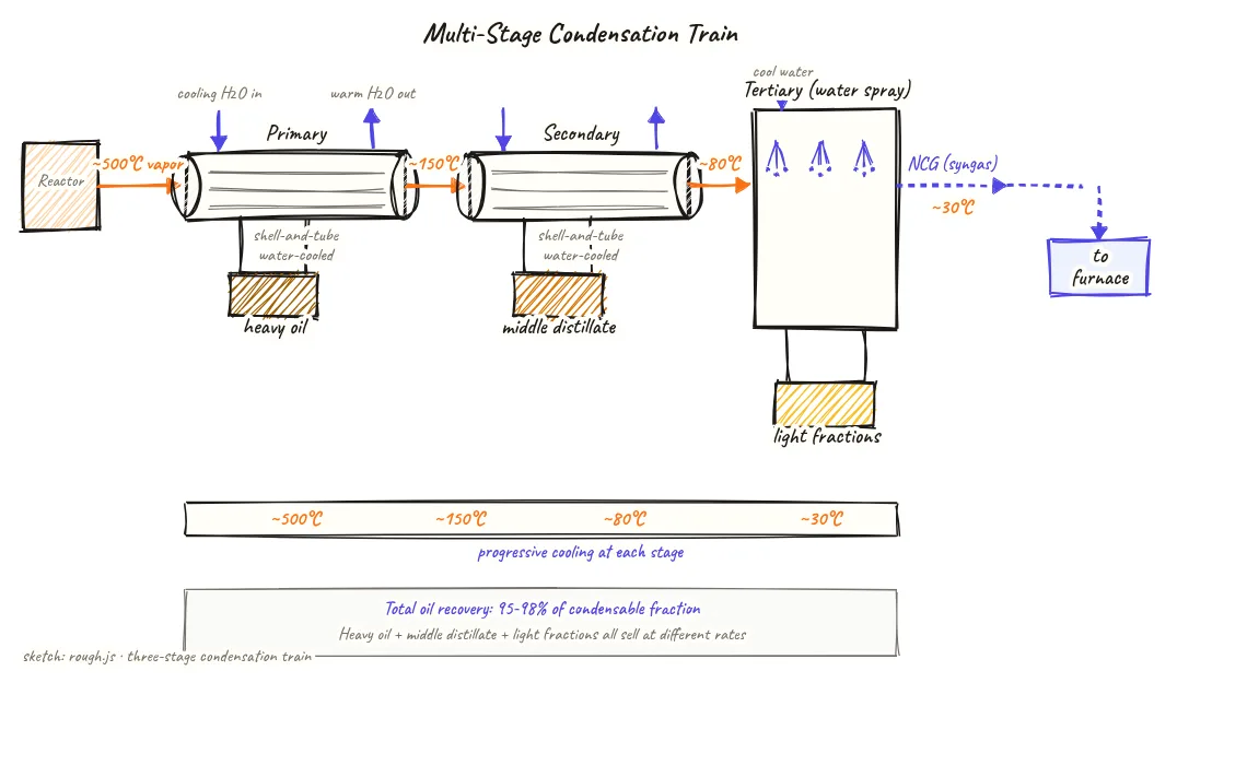
Hot pyrolysis vapors enter the three-stage condenser train at around 500°C and are cooled progressively to 30°C, with different oil fractions dropping out at each stage — heavy oil first, then middle distillate, then light fractions — while non-condensable gas exits to the furnace.
Beyond definitions
Planning to start a Plastic Pyrolysis business?
Get the full business understanding — capex, regulations, machinery, vendor questions, and risk checks before you commit capital.
How to read this sketch
This is a left-to-right process flow diagram. Vapor flows from left to right, cooling progressively at each stage. Read it as follows:
- Vapor line (top, left to right): Shows the gas flow path from reactor outlet through each condenser. Temperature drops are labelled at each stage.
- Condensers (rectangles): Each stage shown as a heat exchanger block. Cooling water enters from one side (blue arrows in) and exits warmer (blue arrows out).
- Oil drains (downward arrows below each condenser): Condensed liquid drops by gravity into collection tanks below each stage. Product quality label at each drain point (heavy oil, middle distillate, light fractions).
- NCG exit (right end, horizontal arrow): Non-condensable gas that cannot be liquefied exits to the gas holder and furnace burner.
- Temperature labels: ~500°C at entry, ~30°C at exit — the full thermal gradient across the train.
About this sketch
The condenser train is where pyrolysis vapors turn into liquid pyrolysis oil — and where the quality and fractionation of the oil is largely determined. This diagram shows a three-stage design with a primary condenser, secondary condenser, and a tertiary water-spray unit, plus the cooling water loops and oil drain points for each stage.
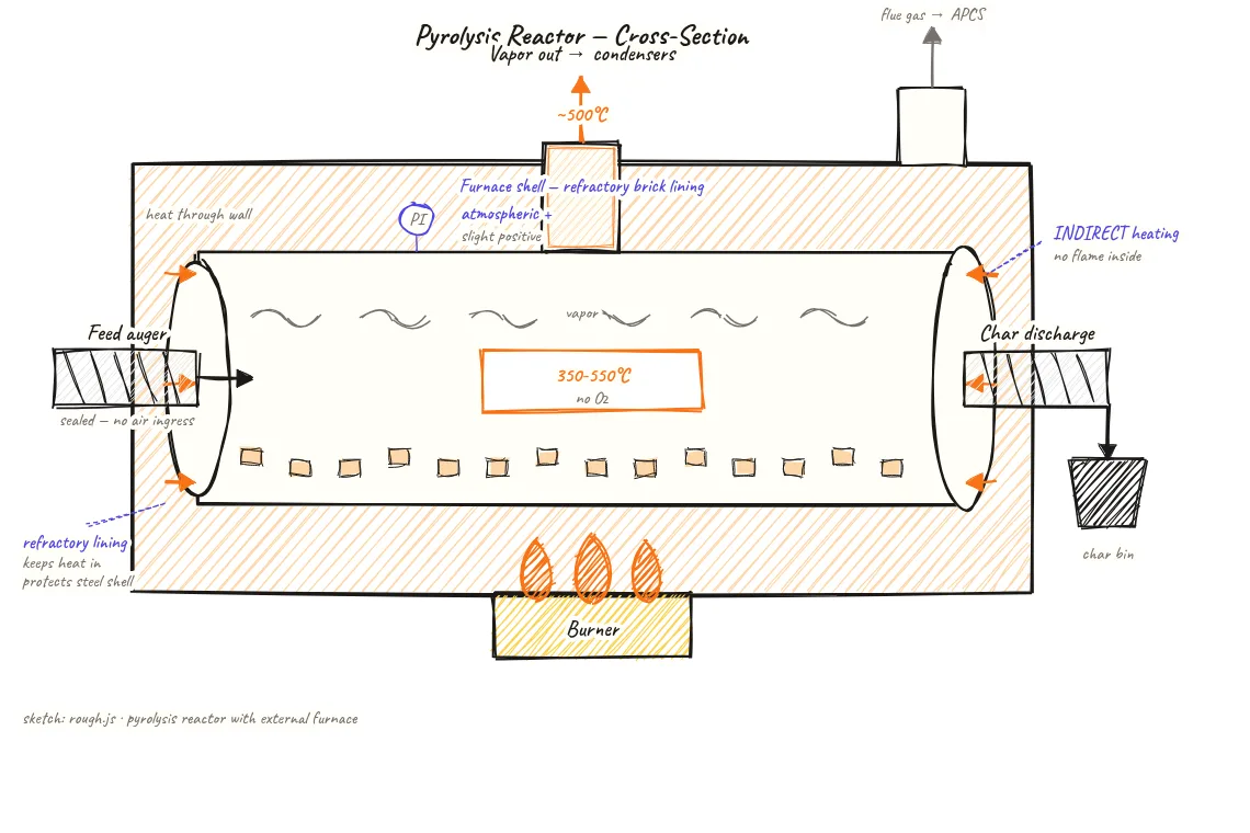
Pyrolysis vapors leave the reactor at roughly 350–500°C carrying a mixture of cracked hydrocarbon molecules, ranging from heavy oil fractions (C15+, boiling point above 300°C) through middle distillates (C10–C14, 180–300°C) to light fractions (C5–C9, below 180°C) and non-condensable gas (NCG, C1–C4 and H2, which will not condense at atmospheric pressure and ambient temperature).
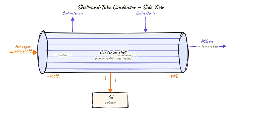
In the primary condenser, vapors first encounter a heat exchanger cooled with water or a cooling medium. Vapors above approximately 300°C condense here — primarily heavy oil and some middle distillate. This first-stage oil is darker, higher-viscosity, and often used for industrial burner applications. Temperature drops from ~500°C to roughly 200°C in this stage. In the secondary condenser, vapors cool further to around 80–100°C, and the middle distillate fraction (the more valuable diesel-like product) condenses. The tertiary stage — often a direct water-spray or shell-and-tube unit — cools remaining vapors to near-ambient (30–40°C), condensing the lightest fractions. Uncondensed gas at 30°C is predominantly NCG with a calorific value of 15–30 MJ/Nm³, which exits to the gas holder and furnace.
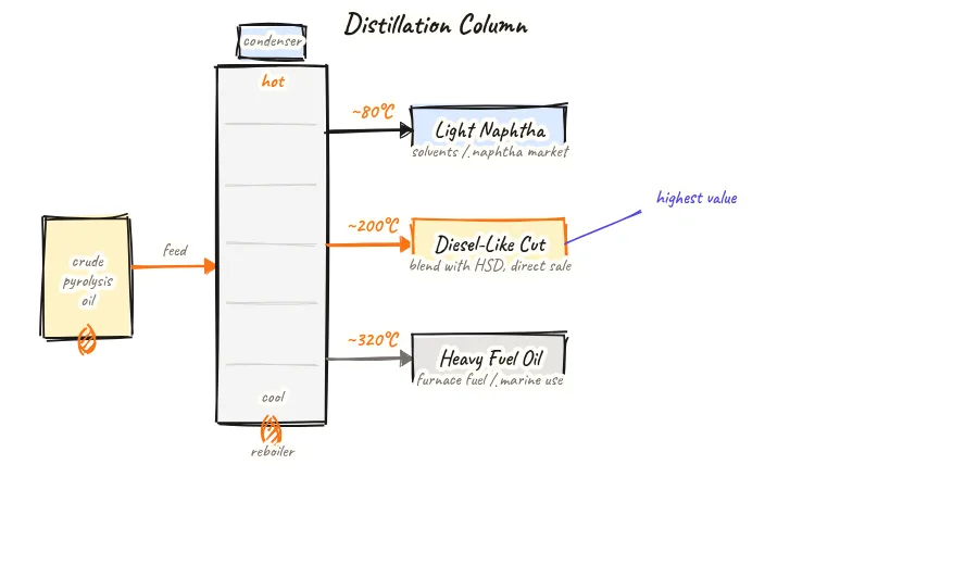
Running three condensers in series rather than a single large condenser gives operators better control over product quality and allows separate collection of different oil grades. Some advanced plants add a fourth stage or a fractionation column to further separate light naphtha from diesel-range fractions.
Key insights
- Three-stage condensation allows separate collection of three oil grades — heavy oil, middle distillate (diesel-like), and light fractions — each with different applications and values.
- Heavy fractions condense first in the primary condenser because they have the highest boiling points; lighter fractions need more cooling and condense in later stages.
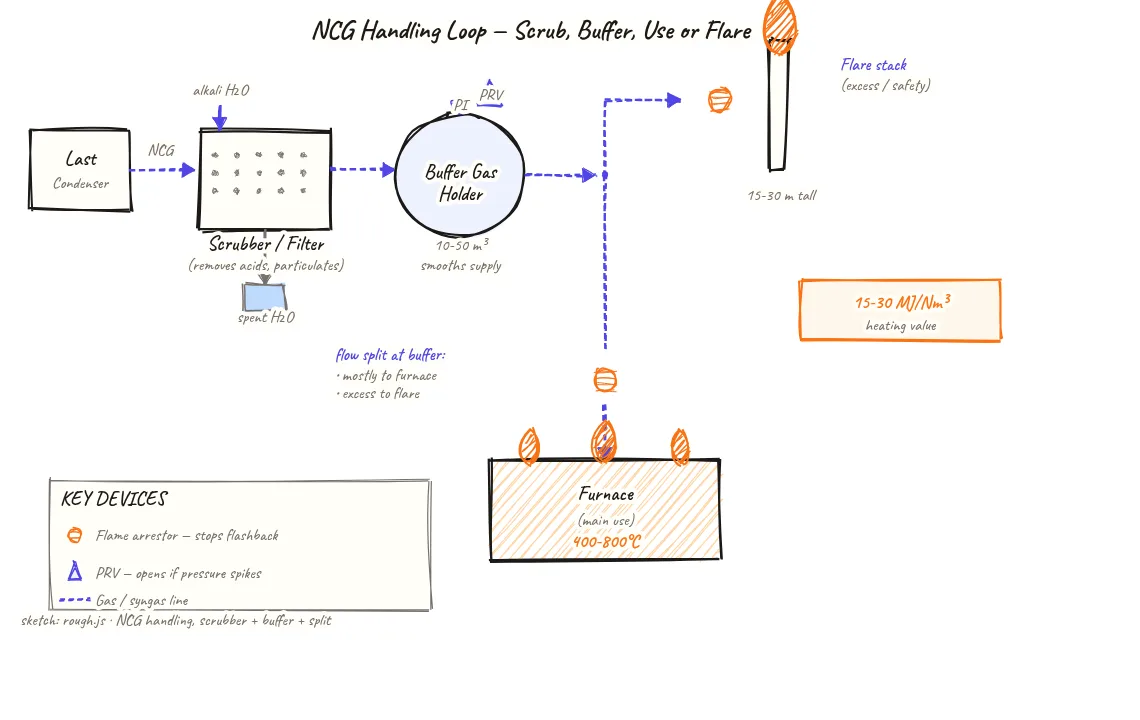
- Non-condensable gas (NCG) exiting the last condenser at 30°C has a calorific value of 15–30 MJ/Nm³ and returns to the furnace as free fuel.
- Fouling of condenser tubes with heavy tar deposits (from high-chlorine or high-additive feedstock) is the main maintenance issue — regular cleaning prevents pressure build-up and yield loss.
- A four-stage or fractionation column upgrade can separate diesel-range fractions from naphtha, improving oil quality for more demanding buyers.