Vapor Path: Reactor → Condenser → Oil Tank
Hot pyrolysis vapors must stay above 350°C from the reactor to the first condenser inlet — premature cooling in the transfer pipe causes heavy hydrocarbons to condense as tar, clogging the pipe and reducing oil yield.
Beyond definitions
Planning to start a Plastic Pyrolysis business?
Get the full business understanding — capex, regulations, machinery, vendor questions, and risk checks before you commit capital.
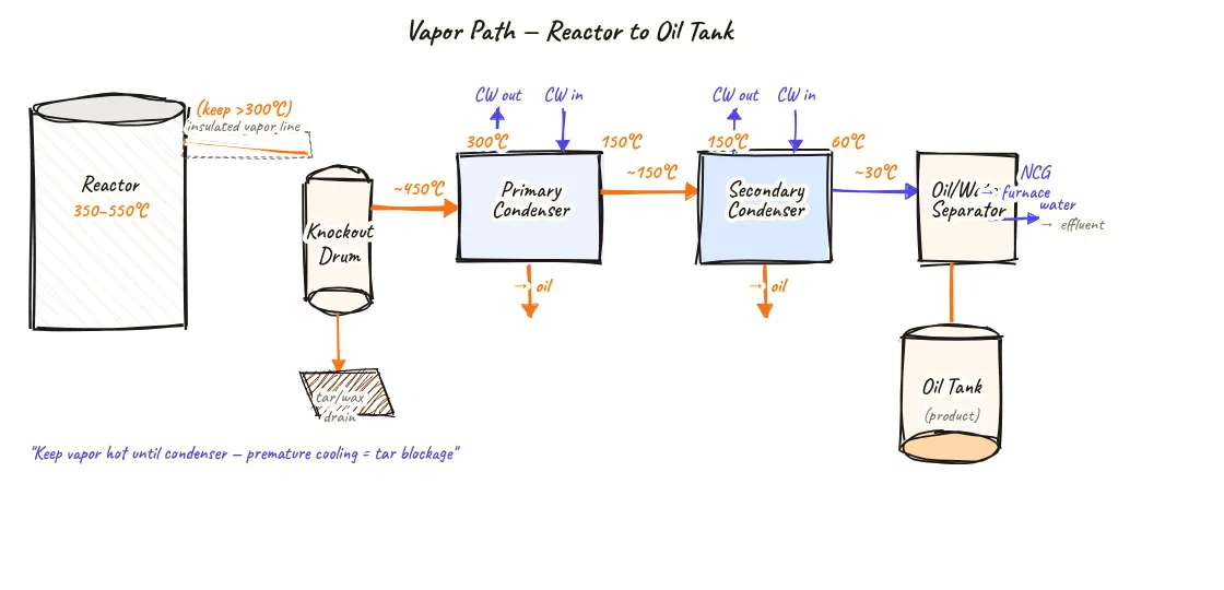
How to read this sketch
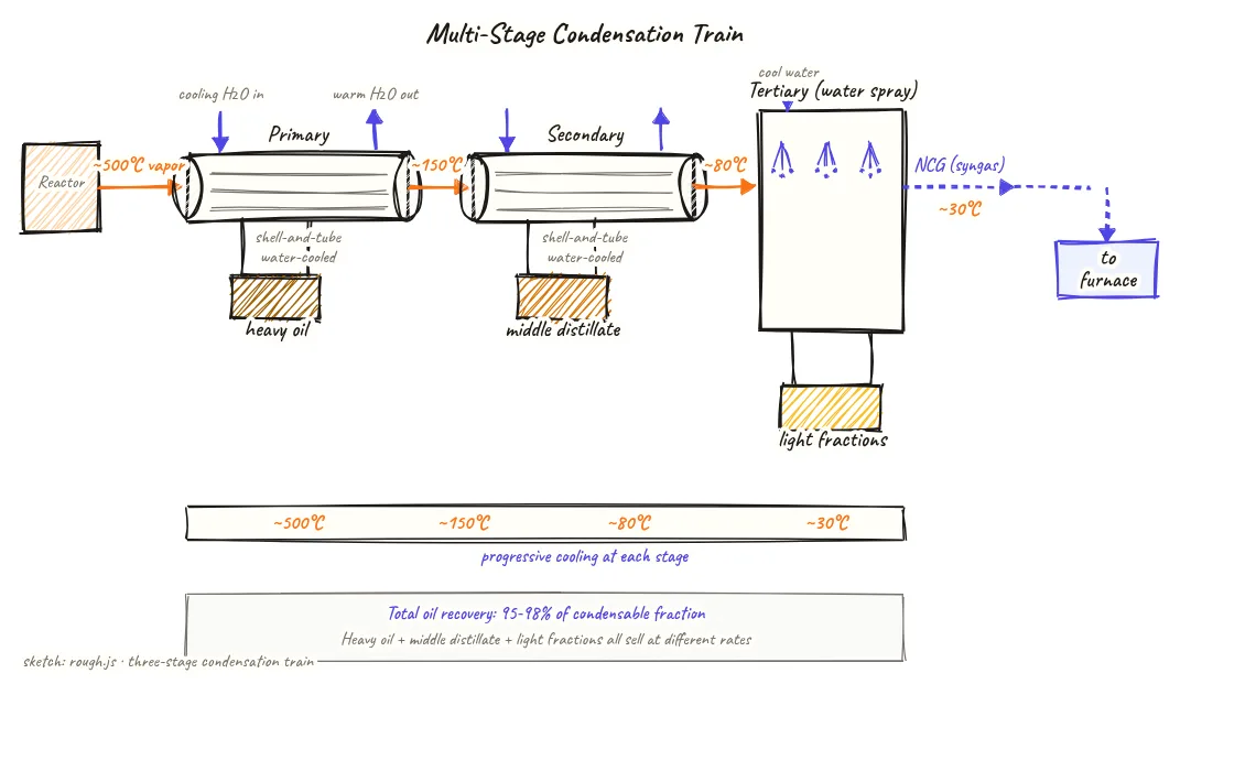
This is a left-to-right flow diagram tracing the vapor path. Temperature labels appear at key points. Read it as follows:
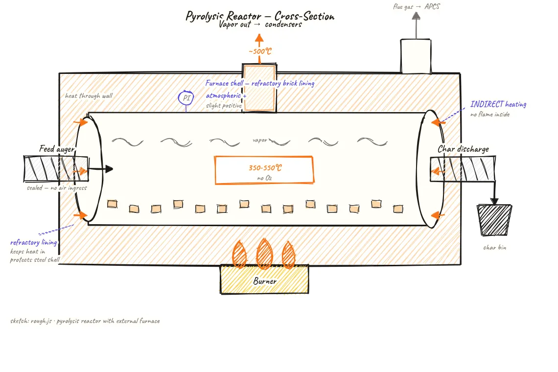
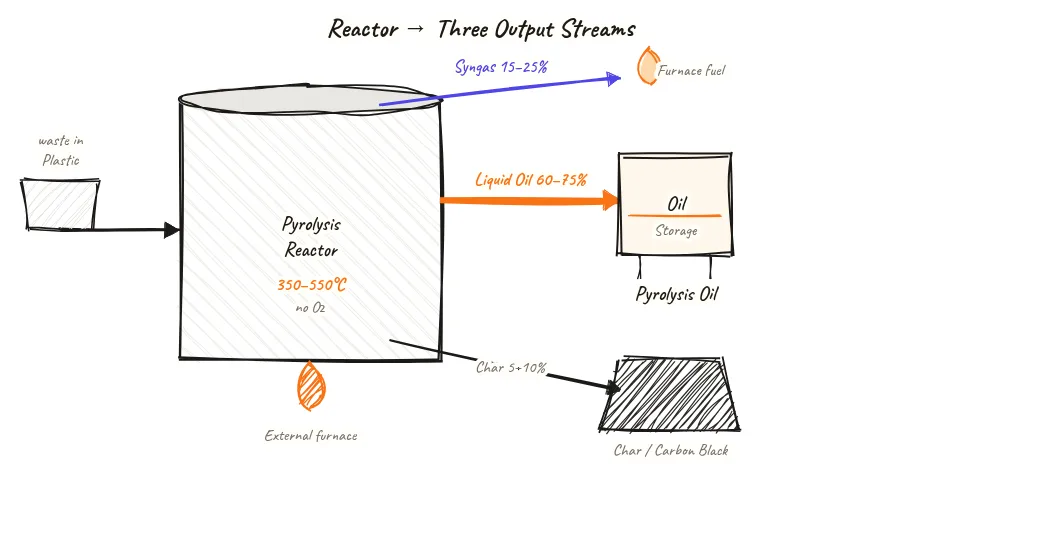
- Reactor vapor outlet (left): Starting point — vapor exits at 350–500°C. Insulated pipe symbol shown on the transfer line.
- Transfer line (dashed insulation marks): Insulated section kept hot until reaching the primary condenser. Warning callout shows tar clog risk if this pipe cools.
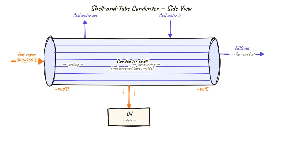
- Primary condenser (first cooling stage): Temperature drops to ~200°C. Heavy oil drain shown below.
- Secondary condenser (second cooling stage): Temperature drops to ~100°C. Middle distillate drain shown below.
- Tertiary condenser (third cooling stage): Temperature drops to ~30°C. Light fractions drain shown below.
- NCG exit (right end): Gas that won't condense exits to gas holder.
About this sketch
The vapor path from the reactor outlet to the condenser train is one of the most maintenance-sensitive sections of a pyrolysis plant. Get it right and vapors flow freely into the condenser; get it wrong and heavy tar deposits gradually clog the transfer pipe, reducing yield and eventually causing a plant shutdown for cleaning.
Hot mixed hydrocarbon vapors exit the reactor through the vapor outlet at the top of the vessel at temperatures of 350–500°C. At this temperature, even the heaviest C20+ hydrocarbons remain in vapor phase. The vapor outlet connects to a transfer line that must remain above the dew point of the heaviest components (approximately 320–350°C for heavy pyrolysis oil fractions) until it reaches the primary condenser. For this reason, the vapor transfer line is always heavily insulated (typically 50–100 mm mineral wool or ceramic fibre) — to prevent radiative and convective heat loss along the length of the pipe run.
If the transfer line is undersized, poorly insulated, or has a low-point sag where vapor can pool, heavy fractions begin condensing on the pipe wall before reaching the primary condenser. These deposits — known as tar or heavy wax — build up progressively and can close off the pipe completely in 4–8 weeks of operation. The remedy is steam or hot-water flushing, which is labour-intensive and takes the plant offline.
Once vapor reaches the primary condenser, deliberate and controlled condensation begins. Temperature drops progressively from ~500°C at condenser inlet to ~200°C at primary outlet, then to ~100°C at secondary outlet, and ~30°C at the tertiary stage. Oil drains below each condenser collect the condensed liquid of each fraction. The NCG exiting the final condenser is clean, light, and goes directly to the gas holder.
Key insights
- The vapor transfer line from reactor to primary condenser must stay above 320–350°C to prevent heavy fraction condensation as tar deposits in the pipe.
- Tar clogging of the vapor transfer line is the most common unplanned shutdown cause in Indian batch plants — proper insulation prevents it.
- Oil fraction quality is determined by the temperature at which it condenses — heavy oil at 200°C, middle distillate at 80–100°C, light fractions at 30–40°C.
- Low-point sags in the vapor transfer line create pooling points where tar builds up fastest — the line should slope continuously upward from reactor to primary condenser.
- Steam or hot-water flushing of the vapor line restores flow after tar blockage, but takes 4–8 hours of plant downtime — prevention is always better.