NCG Handling Loop with Flare and Burner
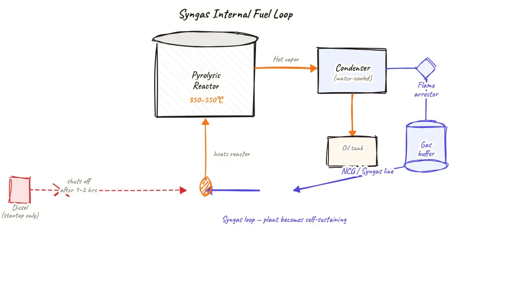
Non-condensable gas (NCG) from the pyrolysis condenser train is cleaned, stored in a gas holder, and routed to the furnace as free fuel — with a flare stack handling any excess safely. This loop is what makes the plant self-sustaining after startup.
Beyond definitions
Planning to start a Plastic Pyrolysis business?
Get the full business understanding — capex, regulations, machinery, vendor questions, and risk checks before you commit capital.
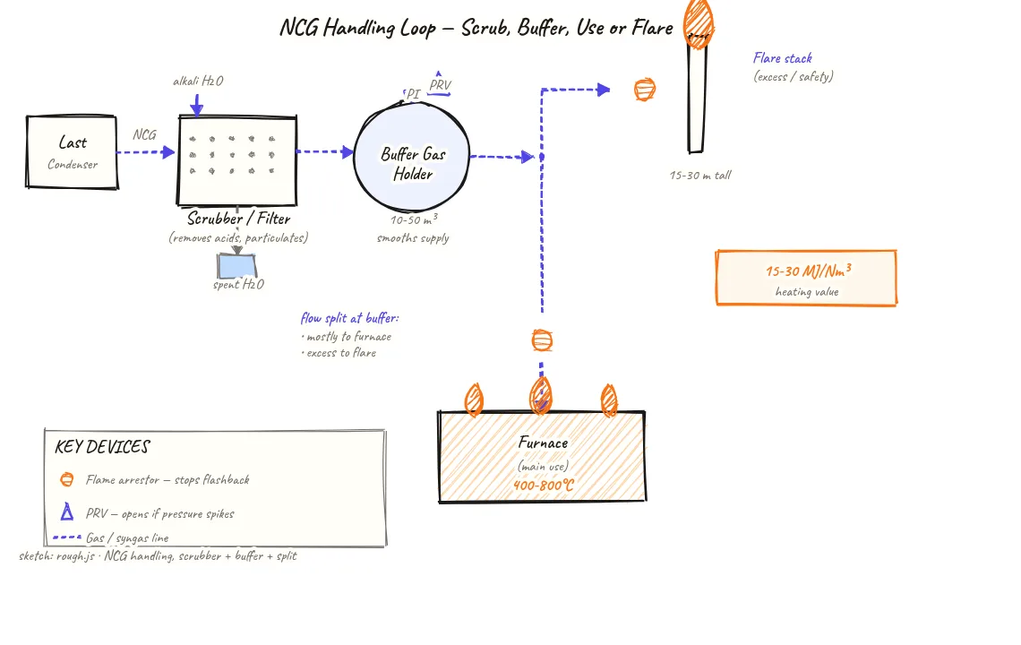
How to read this sketch
This is a left-to-right flow diagram with a branch at the gas holder. Read it as follows:
- Gas source (left): NCG exits the last condenser and enters the scrubber/filter.
- Gas holder (centre): Buffer storage. PRV on top (pressure protection). Flame arrestor on both the inlet and both outlet lines.
- Primary path (lower right): Gas line to the furnace burner — the main consumption path during normal operation.
- Secondary path (upper right): Gas line to the flare stack — activated when the furnace cannot consume gas fast enough or during emergency venting.
- Flame arrestors (triangles on lines): Present on both outlet lines. Critical safety device — prevents flame from propagating back into the gas holder.
- Calorific value label: 15–30 MJ/Nm³ — the energy content of the NCG, comparable to low-grade natural gas.
About this sketch
Non-condensable gas (NCG) is what is left after the condenser train has cooled pyrolysis vapors to near-ambient temperature. This gas — a mixture of methane, ethane, propane, hydrogen, and CO — cannot be liquefied at atmospheric pressure and ambient temperature, but it has a calorific value of 15–30 MJ/Nm³, making it a valuable fuel for the furnace that heats the reactor.
The NCG handling loop starts at the outlet of the last condenser. Gas first passes through a scrubber/filter that removes residual oil droplets, acid gases (HCl from any PVC contamination), and particulates. Clean gas enters a buffer gas holder — a low-pressure floating-dome or bag-type vessel that stores enough gas to smooth out production variations within a batch cycle.
From the gas holder, two paths branch. The primary path leads to the furnace burner: the gas is metered and burned to heat the reactor, making diesel or LPG use unnecessary after the startup phase. A flame arrestor on each line before the burner and before the flare prevents any flame front from travelling back upstream into the gas holder. A pressure relief valve (PRV) on the gas holder protects against overpressure if the furnace cannot consume gas as fast as it is generated — which can happen if a furnace burner trips mid-batch.
The flare stack provides the secondary (safety) path for any gas that cannot go to the furnace — excess production, emergency venting, or gas during startup before the furnace is ready to consume it. CPCB norms require the flare to have a continuously burning pilot flame to ensure complete combustion rather than direct venting of unburned hydrocarbons. Most plants have a simple pipe flare with a gas pilot at 10–20 m height.
Key insights
- NCG with 15–30 MJ/Nm³ calorific value replaces diesel as the primary furnace fuel once the plant reaches steady state — this is the core energy self-sufficiency of plastic pyrolysis.
- Flame arrestors on every NCG line are non-negotiable safety devices — they prevent flame from travelling upstream into the gas holder from either the furnace or the flare.
- The buffer gas holder smooths out NCG production variations within a batch cycle, ensuring steady pressure and flow to the furnace burner.
- The flare stack must have a continuously burning pilot flame under CPCB requirements — unburned NCG venting directly to atmosphere is an air pollution violation.
- A PRV on the gas holder is the last line of protection against gas holder overpressure if both the furnace burner and flare are unavailable simultaneously.