Hopper → Rotary Valve → Reactor Feed
Pre-processed granulated plastic flows from the storage hopper through a rotary valve airlock into the reactor via a feed auger — the rotary valve controls feed rate while blocking air from entering the reactor during loading.
Beyond definitions
Planning to start a Plastic Pyrolysis business?
Get the full business understanding — capex, regulations, machinery, vendor questions, and risk checks before you commit capital.
How to read this sketch
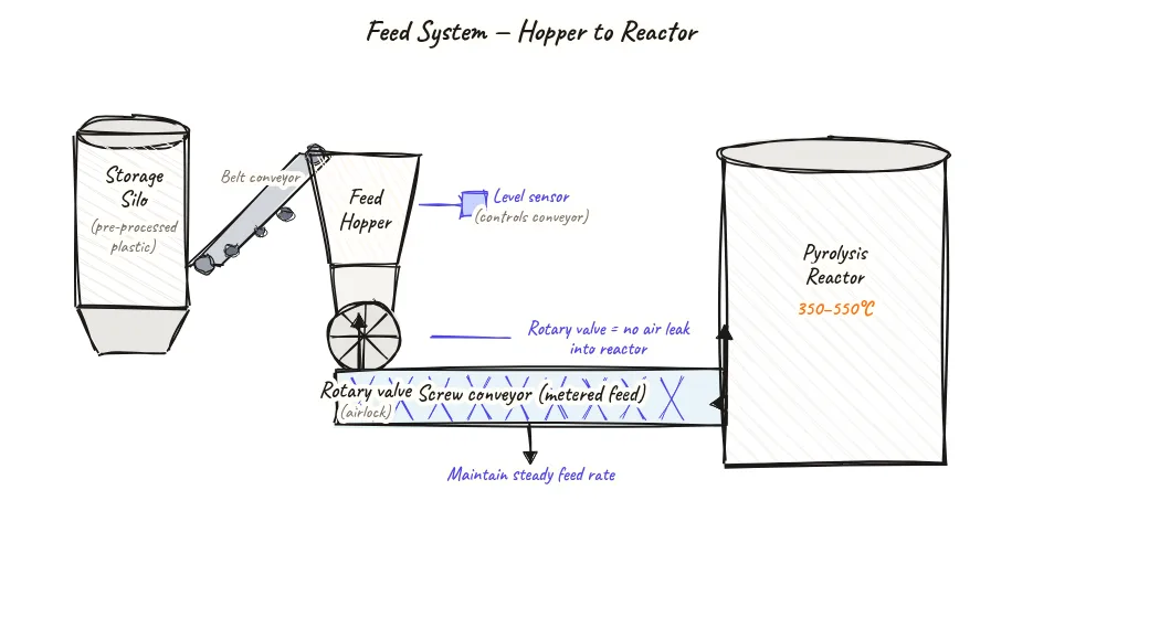
This is a top-to-bottom-to-side flow diagram. Read it from top downward then rightward:
- Hopper (top): Conical vessel holding granulated feedstock. Level sensor shown on the side.
- Rotary valve (below hopper): Circular cross-section showing the 8-vane rotor inside the housing. Rotation arrows show the vane movement direction. Sealing at both sides of the vane shown.
- Feed auger (horizontal, leading to reactor): Screw conveyor moving material from rotary valve outlet to reactor inlet.
- Reactor inlet (right end of auger): Where plastic enters the reactor. Sealed connection prevents air ingress at the junction.
- Label: 'Steady feed rate + no oxygen in = stable reactor operation' — the operational goal the entire system achieves.
About this sketch
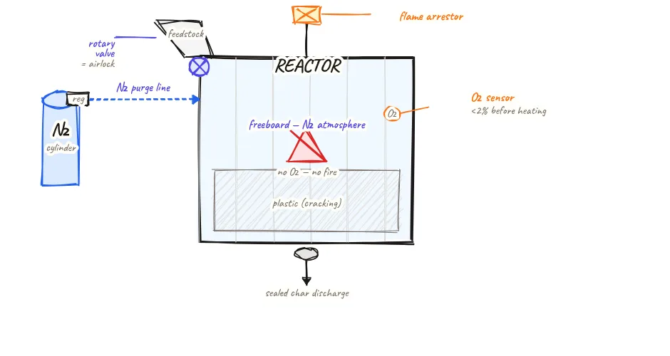
Feeding plastic into a pyrolysis reactor is not as simple as opening a chute. The reactor must remain sealed and oxygen-free at all times during operation, but plastic must enter continuously (in continuous plants) or in controlled batches. The hopper → rotary valve → feed auger system solves this by providing a controlled, air-sealed feed path.
The storage hopper at the top holds a buffer supply of pre-processed granulated plastic (typically 1–3 hours of reactor feed). The conical shape directs material to the central outlet without bridging. A level sensor in the hopper alerts the operator when it needs refilling from the pre-processing line output.
Below the hopper, the rotary valve (also called a rotary airlock or star valve) is the critical sealing element. It consists of a rotor with vanes (typically 8 vanes) rotating inside a housing. As each vane pocket passes the hopper outlet, it fills with plastic granules; as the vane pocket rotates to face the feed auger below, it deposits the granules and closes again behind them — creating a continuous, sealed transfer. The rotary valve body is sealed against air ingress through the valve shaft and housing. The rotation speed controls feed rate in kg per hour.
The feed auger moves granules from the rotary valve outlet into the reactor through a horizontal or inclined screw conveyor. The screw conveyor housing is sealed and can also be purged with nitrogen if feed composition requires extra oxygen exclusion assurance. The combined rotary valve + feed auger system maintains the reactor's positive-pressure atmosphere while continuously adding feedstock — essential for uninterrupted continuous operation.
Key insights
- The rotary valve is the critical air seal in the feed system — a worn or damaged rotary valve allows air to enter the reactor, lowering yield and creating safety risk.
- Feed rate through the rotary valve is controlled by its rotation speed — most plants use a variable-speed drive to adjust feed rate based on reactor temperature feedback.
- For batch reactors, the rotary valve is not needed — the batch is loaded manually or by conveyor into the cold reactor before sealing. The rotary valve is specific to continuous feed designs.
- The storage hopper provides operational buffer — allowing the pre-processing line to have minor stoppages without immediately starving the reactor.
- Bridging in the hopper (plastic particles arching across the hopper outlet) is a common issue with irregularly shaped granules — adding a vibrator or agitator to the hopper prevents feed interruption.