Plastic Pyrolysis Plant — Block Flow
The complete process path of a plastic pyrolysis plant in one diagram — from incoming waste plastic through every machine to finished oil, char, and recycled syngas fuel.
Beyond definitions
Planning to start a Plastic Pyrolysis business?
Get the full business understanding — capex, regulations, machinery, vendor questions, and risk checks before you commit capital.
How to read this sketch
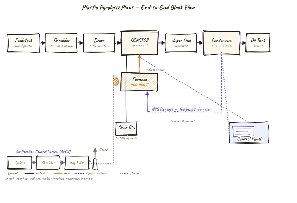
This is a left-to-right block flow diagram. Each rectangle is a process unit or storage vessel. Read it as follows:
- Solid arrows (horizontal flow): Show the main process path from feedstock to products.
- Orange blocks: Highlight the reactor — the core thermal conversion unit.
- Looping arrow (NCG to Furnace): Shows the self-sustaining fuel loop — syngas from the condenser train feeds back to heat the reactor.
- Downward arrows: Show product off-takes — oil from the condenser, char from the reactor bottom, gas to stack.
- Control panel (bottom-right): Connected to all blocks, representing the monitoring and control layer that sits above the process.
About this sketch
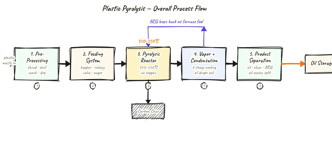
A block flow diagram (BFD) is the starting point for understanding any chemical process — it shows what happens in what order without getting into pipe sizes or instrument details. This BFD traces the full path of plastic waste through a pyrolysis plant in twelve labelled blocks connected by directional arrows.
Material enters as mixed plastic waste and is first reduced in size by a shredder (typically to 50–150 mm chunks), then passed through a rotary drum dryer to bring moisture below 1% — high moisture causes steam spikes and pressure surges in the reactor. From the dryer, material feeds into the reactor, which operates at 350–550°C in the absence of oxygen. Long polymer chains thermally crack into smaller molecules that exit as mixed vapors.
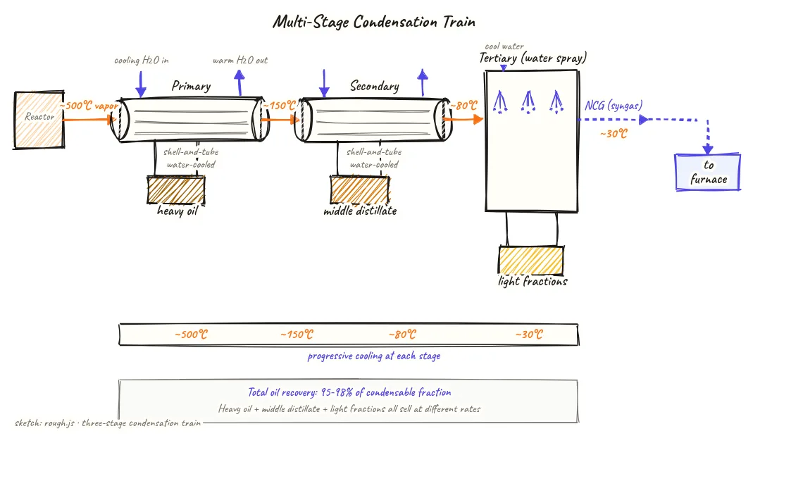
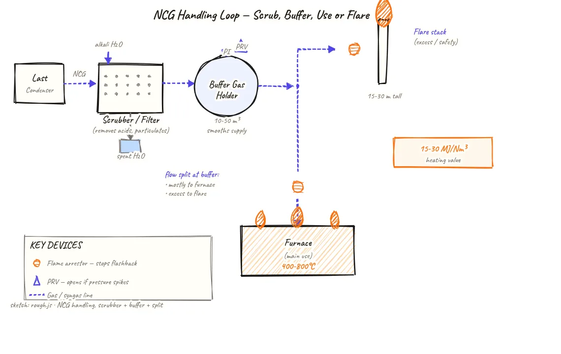
These vapors travel down a vapor line into a condenser train — typically two or three stages — where they cool progressively from ~500°C to ~30°C. Heavier fractions drop out first (heavy oil), followed by middle distillates, then light fractions. Non-condensable gas (NCG), also called syngas, is too light to liquefy and exits the last condenser as a gas. This gas — with a heating value of roughly 15–30 MJ/Nm³ — is cleaned and fed back into the furnace as fuel, making the plant self-sustaining after the first hour or two of diesel startup.
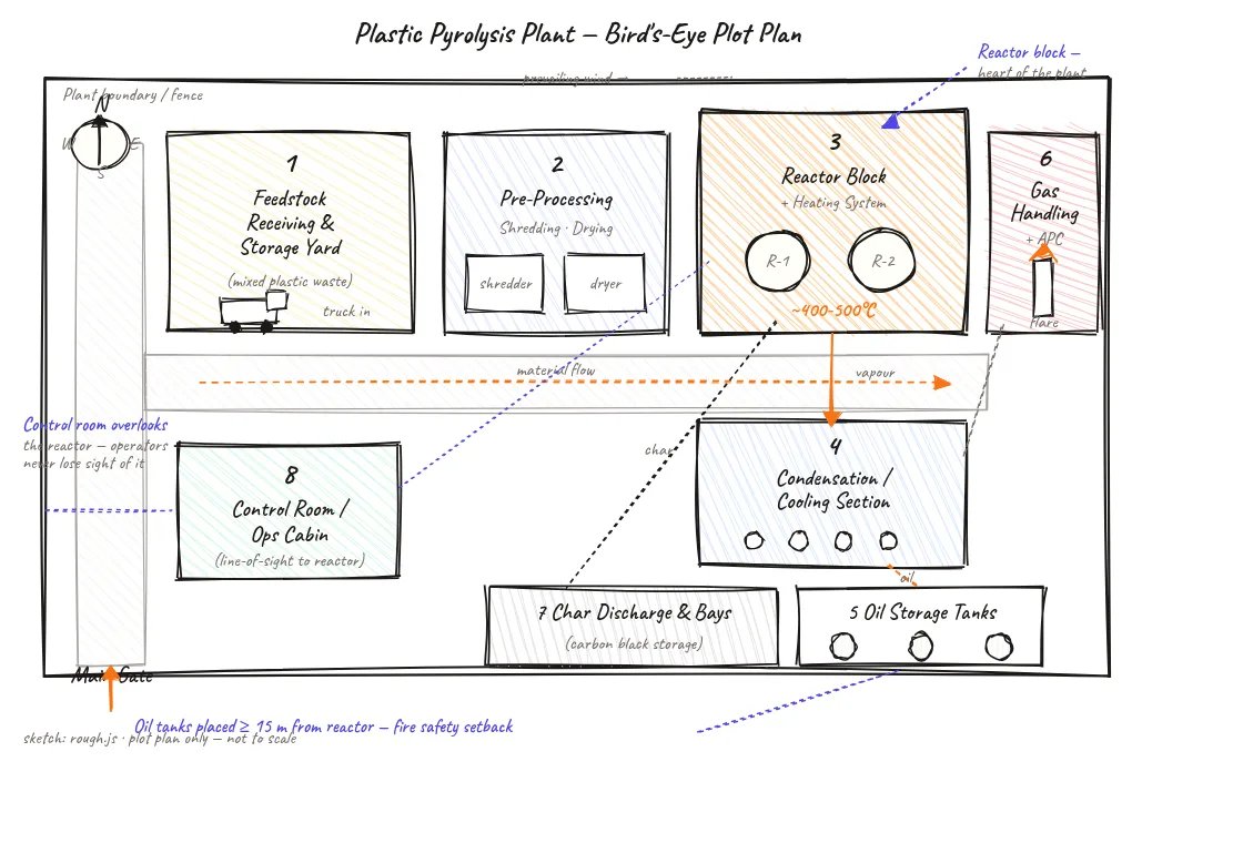
Solid char settles at the reactor bottom and is discharged to a char bin via a sealed screw conveyor after the reactor cools below 150°C. Flue gases from the furnace pass through the Air Pollution Control System (APCS) before exhausting through a 15–30 m stack. A control panel (or PLC/SCADA system) monitors and manages all twelve process blocks from a central location.
Key insights
- Feedstock must be dried below 1% moisture before entering the reactor — moisture creates steam pressure surges that can trip safety shutdowns.
- Non-condensable gas (syngas) from the condenser train loops back as furnace fuel, making the plant energy self-sufficient after startup.
- The condenser train separates pyrolysis vapors into fractions by cooling progressively — heavy oil, middle distillate, and light fractions come out at different stages.
- Char discharges after the reactor cools below 150°C — discharging at higher temperature risks reignition.
- All twelve process blocks feed into a single control panel, so one operator can monitor the entire plant from one location.