Oil Storage Tank Yard
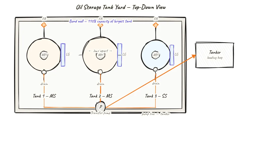
A top-down view of the oil tank yard shows how pyrolysis oil tanks are arranged inside a common bund wall, with vents, flame arrestors, level gauges, and a transfer pump feeding a tanker bay — meeting the statutory fire-safety and spill-containment requirements.
Beyond definitions
Planning to start a Plastic Pyrolysis business?
Get the full business understanding — capex, regulations, machinery, vendor questions, and risk checks before you commit capital.
How to read this sketch
This is a top-down (plan view) of the oil storage yard. Read it as follows:
- Bund perimeter (outer rectangle): The spill containment wall. All tanks must be inside this boundary.
- Tanks (circles or rectangles): Individual storage tanks shown from above. Vent pipes shown as small projections from the tank top with flame arrestor symbols.
- Level gauges (vertical lines on tank sides): Monitoring points for each tank's fill level.
- Transfer pump (small box inside bund): Pump that moves oil from storage to the loading bay.
- Tanker bay (outside bund, bottom or side): Where oil tanker vehicles load. A pipe passes through the bund wall with an isolation valve.
- Bund capacity label: Confirms 110% containment requirement is met.
About this sketch
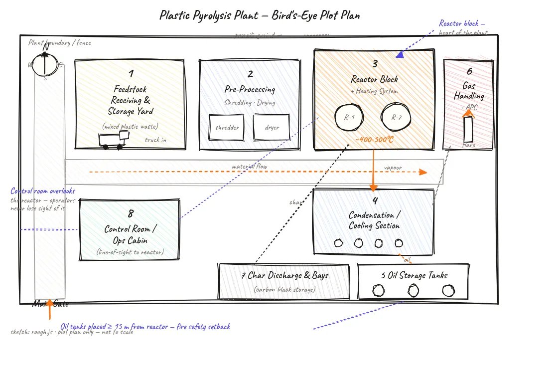
The oil tank yard is one of the two highest-risk zones in a pyrolysis plant (along with the reactor block), and its layout directly affects both safety and statutory compliance. This top-down view shows how a typical Indian pyrolysis plant organises its oil storage area with the required safety infrastructure.
The bund wall is the primary containment feature — a low concrete or brick perimeter built to hold at least 110% of the largest tank's capacity. In practice, most plants size the bund to hold all tanks combined, as this simplifies inspection compliance. The bund floor is typically impermeable concrete sloped toward a sump drain with a normally-closed valve — this prevents spilled oil from reaching the ground while allowing accumulated rainwater to be released after inspection.
Each tank has a vent pipe with a flame arrestor fitted at the outlet. Pyrolysis oil vapors are continuously generated in the tank headspace as the oil warms through the day. The vent allows pressure equilibration while the flame arrestor prevents any external flame from entering the tank through the vent. Without this device, a static spark at the vent outlet could cause a flash-back into the headspace.
A level gauge on each tank allows operators to monitor fill levels from outside the bund without having to climb tanks. Fixed-type magnetic float level gauges or sight-glass gauges are standard. The transfer pump inside the bund moves oil from storage tanks to the tanker loading bay — which sits outside the bund wall at a safe distance. The loading connection typically has a vapour return line to the tank to prevent vapour release during loading.
Key insights
- The bund wall must contain 110% of the largest single tank's volume — this is non-negotiable for PESO compliance and required for the Consent to Operate (CTO) inspection.
- Flame arrestors on every vent pipe prevent flash-back from external ignition sources — missing flame arrestors on even one tank is a compliance failure on PESO inspection.
- The transfer pump is inside the bund (not outside) so any pump seal leak is contained within the bund rather than spreading to surrounding ground.
- The tanker bay is outside the bund and separated by an isolation valve — preventing tanker vehicle accidents from affecting the bund integrity.
- A bund sump drain valve should be normally closed and only opened under supervision after confirming no oil is present — routine rainwater drainage is the legitimate use.